
To improve collaboration efficiency between CAD and AiHouse for custom cabinets, wardrobes, and similar cabinet products, the system provides CAD linkage capability. Designers can push cabinets or panels from 3D into CAD for editing, and then read CAD changes back into 3D and apply them to the current cabinet. This reduces repetitive work such as "edit once in CAD, then rebuild it again in AiHouse."
Entry Point:
Custom Cabinet Module / Top Toolbar / CAD Linkage
Function Scope:
Supports pushing currently selected panels in AiHOUSE to CAD to generate a front-view panel workspace
Supports modifying panels in CAD and applying recognizable CAD changes back to the current 3D panel
Supports panel contour changes such as irregular single-panel shapes, holes, slots, corner cuts, and clearances
Performs CAD Bridge connection checks and exception prompts before use
I. Feature Entry
1. Open the CAD Linkage Panel
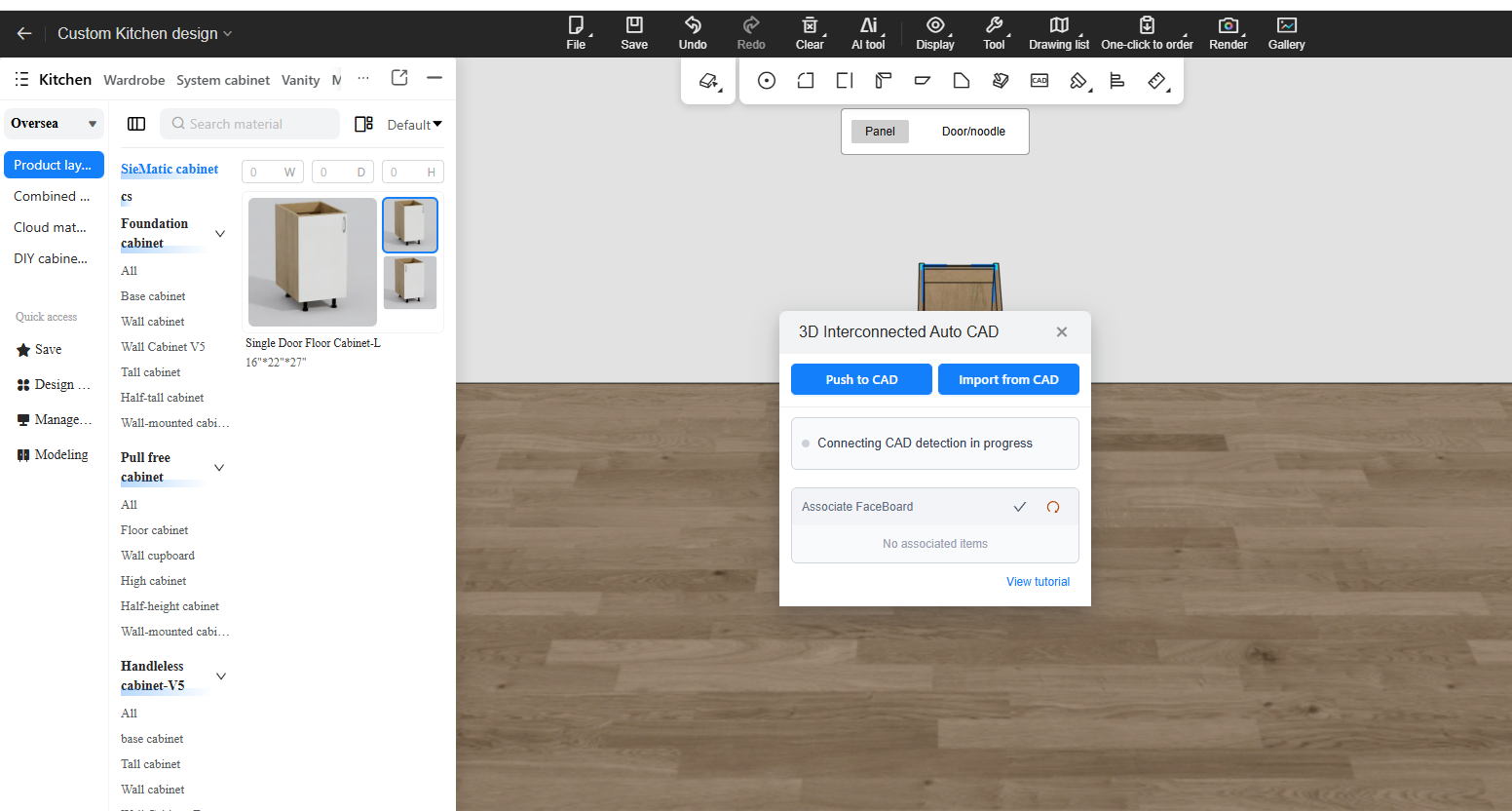
After entering AiHouse, go into a whole-house customization module such as custom wardrobes or kitchen cabinets, and switch to Panel Mode.
Then click CAD Linkage on the top toolbar.
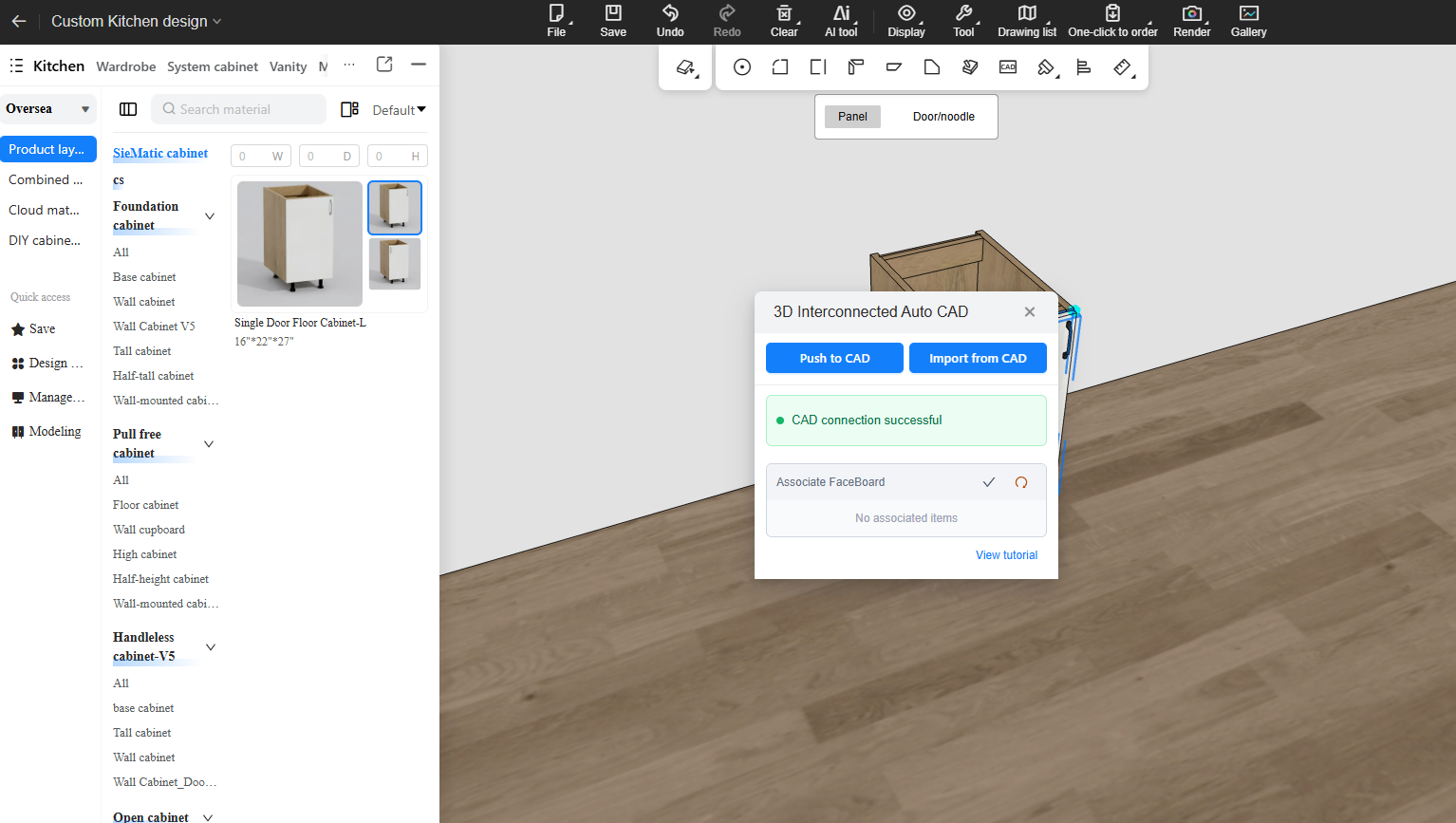
After clicking it, the CAD Linkage panel opens. It is used to connect to CAD, push panels to CAD, or read CAD changes and apply them back to AiHouse.
2. Select the Panel Before Use
Before using CAD linkage, first select the panel that needs to be linked in AiHouse.
If no panel is selected, the system may not be able to identify which object should be pushed to CAD.
II. Preparation Before Use
1. Open AutoCAD
Before use, open AutoCAD first and confirm that AutoCAD has completed authorization and initialization.
If AutoCAD is not open, not authorized, or is currently busy, CAD linkage may not be able to connect properly, and AiHouse will display corresponding prompts.
2. Install AutoCAD Plugin
CAD linkage depends on the local AutoCAD Plugin to communicate with AutoCAD.
Download link:
https://sunvega-automate.3vjia.com/sunvega-autocad/latest/sunvega-autocad.exe
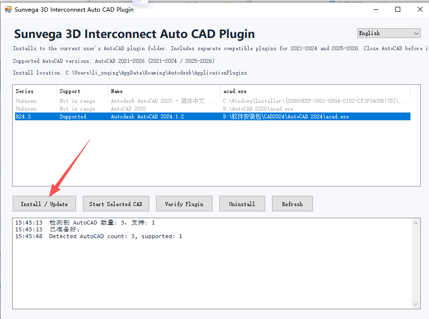
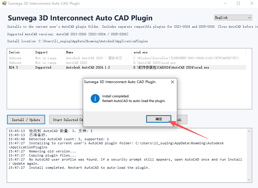
After downloading, double-click the plugin installer and click Install / Update.
After installation or update:
-Open CAD
-Click Detect Plugin
If prompted inside CAD:
-Choose Always Load
-Then click Detect Plugin again
3. Perform a Connection Check
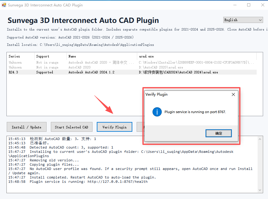
After opening the CAD Linkage panel, the system automatically performs a connection check.
Once the check succeeds, you can continue with panel recognition and push operations.
III. AiHouse Panel CAD Linkage
1. Recognize the Current Panel
After selecting a panel in the 3D mode, click Recognize Current Panel.
The system scans panel data from the current selection. If recognition succeeds, the panel shows how many recognizable panels were found.
If no panel is recognized, reselect the full panel, or enter panel editing mode and try again.
2. Push to AutoCAD
Click Push to AutoCAD.
Multiple panels can be selected and pushed at one time.
The system creates a workspace for the current panel in CAD, including the panel outline and required business identifiers.
The following content is mainly generated in CAD:
| Content | Description |
|---|---|
| Panel Workspace | The CAD editing area for the current panel |
| Original Panel Outline | A reference to the original 3D panel; not recommended as the direct basis for reverse application |
| Structural Objects | Panel structure projected from the 3D panel |
| Graphic Identifiers | Used to match the original 3D panel with the CAD modification result during readback |
3. Edit in CAD
Users can move, scale, or adjust the contours of the system-generated objects in CAD.
The corresponding changes can be previewed in real time on the 3D side.
4. Apply Back to AiHouse
After confirming that the readback result is correct, click Save Changes.
PS: CAD linkage writes back to the currently linked panel by default. It does not create a second new panel.
5. Import from CAD
If you have other pattern files, you can click Import from CAD in the AiHouse CAD Linkage panel.
IV. Common Questions
1. CAD Graphic Type Restrictions
Only closed graphics built from the following are supported:
- Straight lines
- Polylines
- Circles
- Arcs
- Rectangles
Unsupported types such as ellipses and splines are currently not supported by the system.
Only when a closed graphic is created can it be correctly mapped back into AiHouse.
2. CAD Bridge Port Occupied Prompt
Error example:
WH CAD Native Bridge failed to start: Usually each socket address (protocol/network address/port) is allowed to be used only once.
3. Unable to Read CAD Changes
Possible causes:
- The CAD graphic is not closed
- The modified object is not in the current panel workspace
- The modified object is not selected in 3D
- AutoCAD is busy, or the COM call was temporarily rejected
- A pattern was pushed from 3D to CAD and then copied into the workspace of another CAD-linked 3D panel
How to handle it:
- Confirm whether the graphic is closed
- Prefer modifying the CAD objects generated by the system
- Wait for AutoCAD to stabilize and then read again
- If synchronization always fails, select the current CAD pattern and run BO once to clear the bound panel from it