
December Feature Update Summary
1.Basic Operations
1.1 Drawing Floor Plan Optimization - Import CAD File, Add Vector Tracing
1.2 Object Operation Toolbar For Loose Furniture Extended To The Cabinet Customization Module
1.3 My Projects - 2D/3D Display Preferences
2.Rendering & Lighting
2.1 Album Interface Update
3.Customization
3.1 Left-Side Asset Panel - Default Directory Display Mode
3.2 Asset Square - Drag-And-Drop Parametric Cabinet Assets Maintains Asset Square Directory View
3.3 Assets Support Sorting
3.4 Customization Modules Use New Asset Pop-Up Panel
3.5 Shelf/Vertical Partition Drag-And-Drop Position Snapping Optimization
3.6 JEGA LITE Users Support Installing Hinge/Slide Components
3.7 Special-Shaped Edge Banding Output Logic Optimization
4.Finishing Customization
4.1 Unified Interaction For Entering 2D Design In Customization Modules
4.2 Quick Selection Of Wall Segmentation Lines
4.3 Parametric Ceiling Supports Adaptive Changes By Area
4.4 Ceiling/Wall Increases Arc Line Segment Count Setting
5. Aluminum Doors & Windows
5.1 Glass Hole/Notch Function Design
5.2 Ruler Auto-Jump Function
1. Basic Operations
1.1 Drawing Floor Plan Optimization - Import Cad File, Add Vector Tracing (for All)
Highlight:
After importing a CAD file, a vector image is generated. Users can either let the system intelligently generate the floor plan or choose the manual wall-drawing mode to trace it themselves.
Problem Solved:
Addresses inefficiency when intelligent recognition from CAD import fails.
Steps:
Entry Point 1: Welcome page - Import CAD
Entry Point 2: Left navigation - Floor Plan - Import
Entry Point 3: Top menu - File - Import Floor Plan - Import CAD
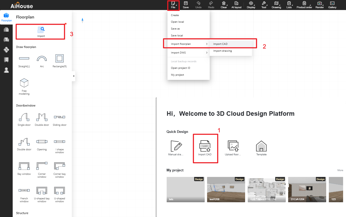
Intelligent Recognition: After selecting the CAD file, choose [Smart Recognition] in the pop-up panel, select the recognition method, click OK. The system will automatically identify the drawing in the file and generate the floor plan.
Manual Wall Drawing:After selecting the CAD file, choose [Manual Drawing] in the pop-up panel, click OK.

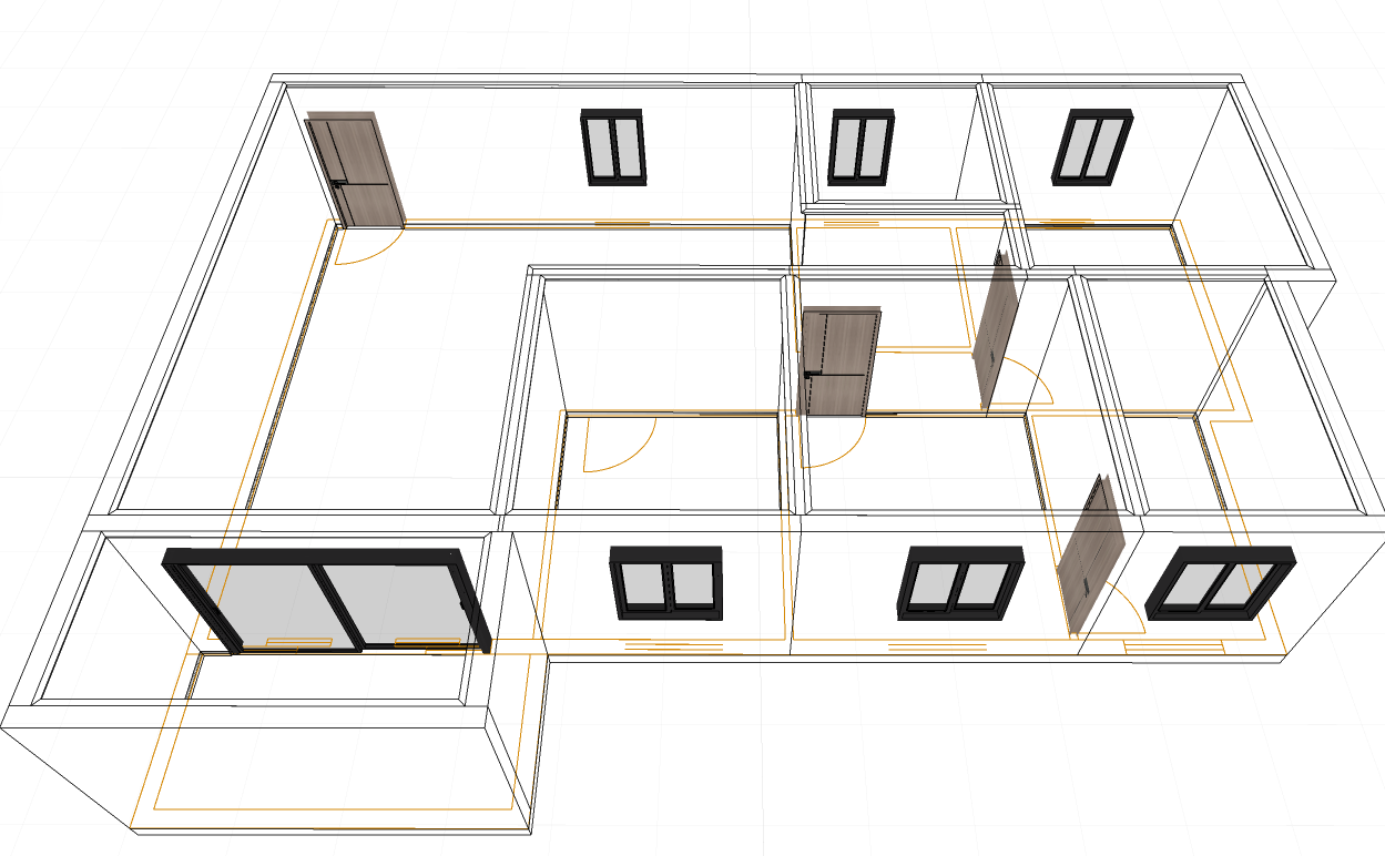
After confirmation, the system generates a vector image. Use the floor plan components in the left navigation to manually draw the floor plan.
Underlay Settings: Manage Tracing Image, Hide Tracing Image, Unlock Tracing Image, Delete Copy Drawing.
Note: The maximum resolution for images generated by this feature is 2K.
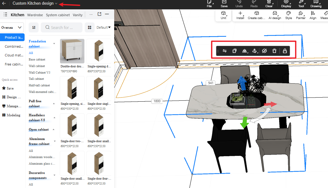
1.2 Object Operation Toolbar For Loose Furniture Extended To The Cabinet Customization Module (for All)
Highlight:
The object operation toolbar for loose furniture is now available in the Whole House module (Customization modules refer to Wardrobe/Kitchen Cabinet, Vanity, Solid Wood, Shower Room). This update aims to reduce the need for switching modules.
Steps:
Click on a loose furniture to perform operations: Replace Product, Copy, Mirror (Left/Right, Front/Back, Up/Down), Move, Rotate, Scale, Group/Ungroup, Align, Hide/Show, Delete, Lock/Unlock.
1.3 My Projects - 2D/3D Display Preferences (for All)
Highlight:
Designers can set their preferred project display method for the project list in "My Project".
Problem Solved:
Addresses the preference of some designers who like to find projects via flat floor plans.
Steps:
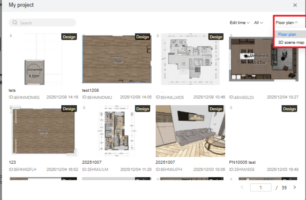
Location: Top menu - File - My Project.
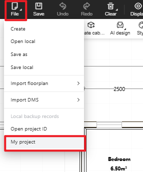
In the [My Projects] dialog, select [Floor Plan]. Once selected, the project images in both the [My Projects] and [Welcome Page] dialogs will display as floor plans.
2.Rendering & Lighting
2.1 Album interface update (for All)
Highlight:
Optimized album interface. Users can freely switch between list view and large image view, preview high-resolution images in full screen, making it more convenient to browse the album.
Problem Solved:
Addresses user feedback regarding loading time when viewing large images by default entering edit mode, improving user satisfaction.
Steps:
From the design page, click Album to enter the new album interface.
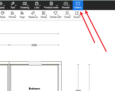
Switch to Large Image View via the icon in the top left corner or by clicking on an image.
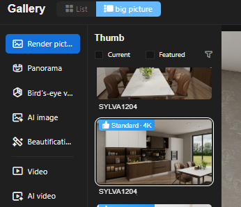
In large image view, click Full Screen for high-definition full-screen preview or exit.

While viewing a large image, click Beautify Image to enter the image editor.

Finally, click Download or Quit.
3. Customization
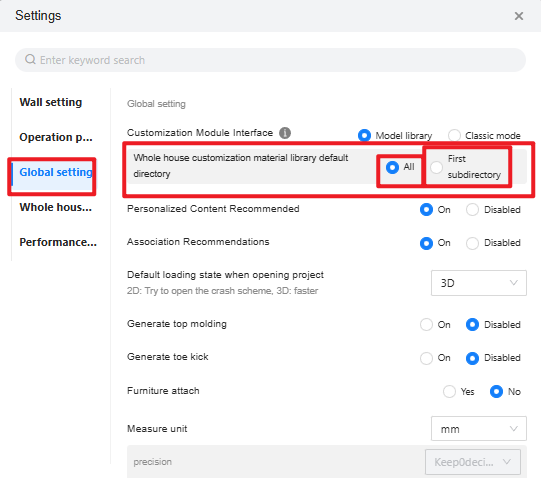
3.1 Left-Side Asset Panel - Default Directory Display Mode (for All)
Highlight:
Designers can configure the asset panel to open showing all sub-directories or just the first sub-directory, based on their viewing habits.
Problem Solved:
Provides a configuration option to address inconsistent designer habits after the update that showed all sub-directories by default.
Steps:
Open a design project, click the top menu - Settings.
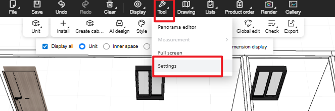
Within the panel: Global Settings -> Asset Library Mode ->Whole house customization material library default directory.
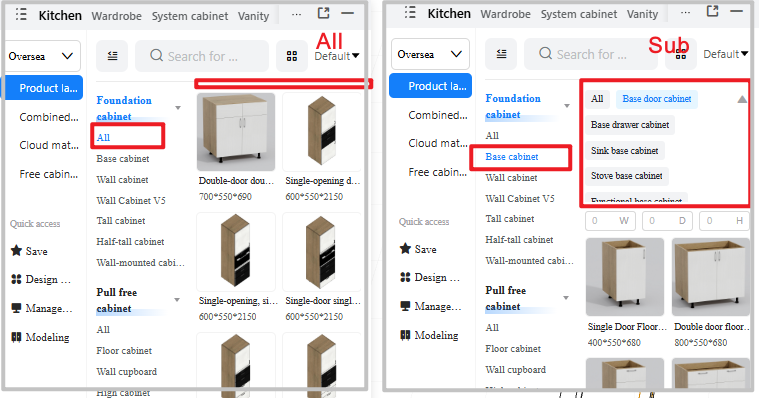
Configure to Default - All: When entering Wardrobe/Kitchen Cabinet, the left-side panel expands all directories showing the asset list.
Configure to First Sub-directory: When entering Wardrobe/Kitchen Cabinet, the left-side panel shows the asset list for the lowest-level sub-directory.
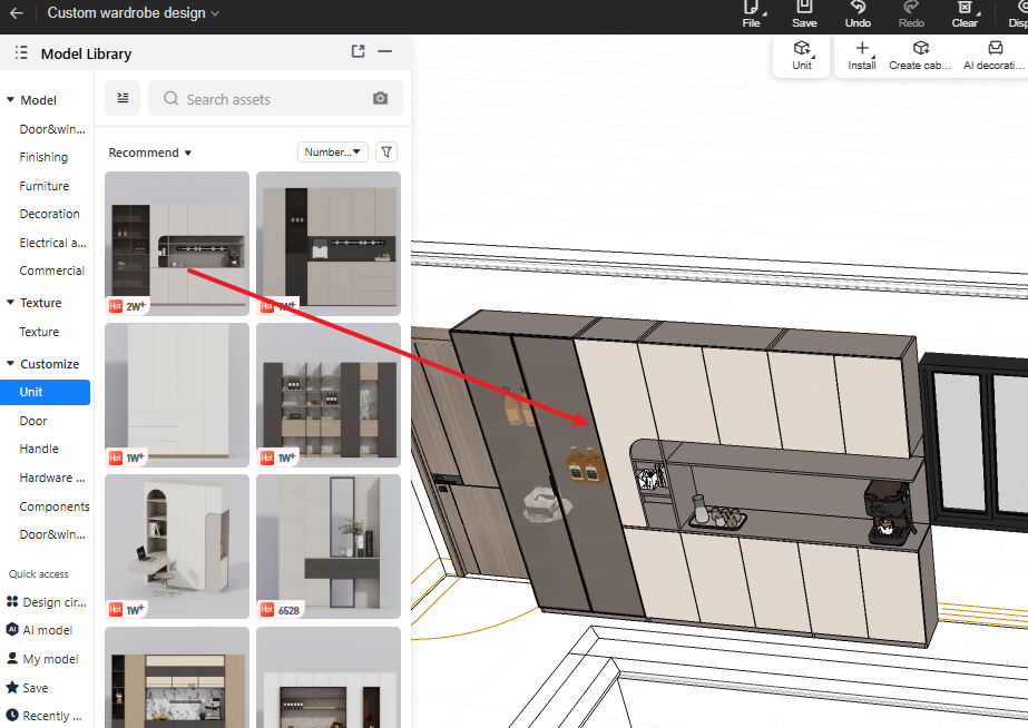
3.2 Asset Square - Drag-And-Drop Parametric Cabinet Assets from Asset Library Maintains Asset Square Directory View (for All)
Highlight:
When dragging a cabinet asset from the Asset Square into the scene, although the system enters the Cabinet Customization module, the left-side asset page remains on the Asset Square view, allowing designers to continue dragging assets
Problem Solved:
Previously, when using Asset Square in the Basic module to drag cabinet assets, the system automatically switched to the Cabinet module and the left panel changed to parametric cabinet assets, causing frequent and cumbersome switching
Steps:
In 3D view, open the left-side Asset Square, click the cabinet category, drag an asset into the floor plan
The system automatically enters the Cabinet module, but the left panel stays on the Asset Square, allowing you to continue dragging and placing assets.
3.3 Assets Support Sorting (for All-New)
Highlight:
Switch sorting methods to display the asset list under the currently selected directory accordingly.
Sorting options: Default / First Upload / Latest Upload / Earliest Updated / Least Updated
Problem Solved:
Previously, Wardrobe/Kitchen Cabinet assets could only be displayed in default order. Now, multiple sorting options help quickly locate assets.
Steps:
Open a 3D project, enter Wardrobe/Kitchen Cabinet design.
Switch the default sorting to another method (e.g., Newest). The assets in the current directory will be displayed according to the selected sort order.

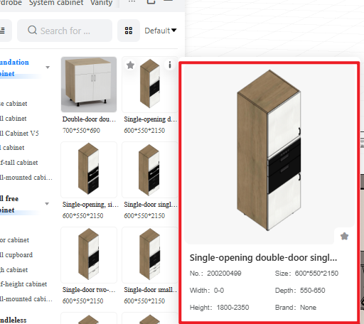
3.4 Customization Modules Use New Asset Pop-Up Panel (for All)
Highlight:
Updated to the new asset panel, optimizing the display interface.
Problem Solved:
After the Asset Square redesign, the Basic module already used the new asset pop-up, but Customization modules still used the old one, causing inconsistencies:
Interaction and visual design were not unified (e.g., copying asset names).
The old pop-up had poor extensibility.
Steps:
Open a 3D project, enter Wardrobe/Kitchen Cabinet design.
Hover the mouse over a wardrobe asset. The new asset panel will appear.
3.5 Shelf/Vertical Partition Drag-And-Drop Position Snapping Optimization (for All)
Highlight:
When a shelf or vertical partition inside a cabinet has a gap from the left/right side panels or back panel, dragging it allows free movement. Users can also directly modify the ruler for precise positioning.
Problem Solved:
Solved the issue where previously, when a shelf/partition had a gap from side/back panels, snapping would always default it back to the left-rear corner position.
Steps:
Open a 3D project, enter Wardrobe/Kitchen Cabinet design.
Modify the dimensions of a cabinet shelf/partition (excluding board thickness) or adjust its ruler values (left/right/front/back for shelves, up/down/front/back for vertical partitions).
When dragging the shelf/partition again, it will not snap back to the left-rear corner. It can be placed as desired, aligned to the centerline, or its precise position can be modified via the ruler.
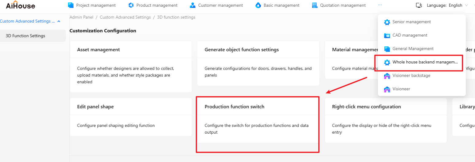
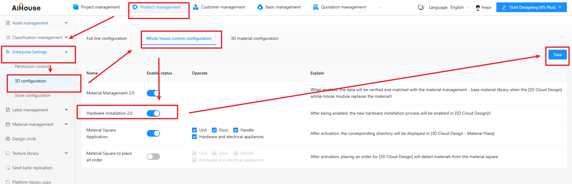
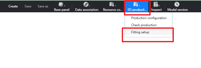
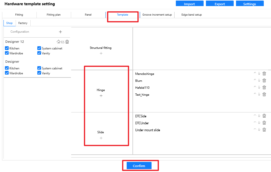
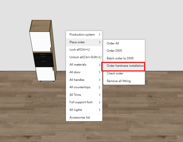
3.6 JEGA LITE Users Support Installing Hinge/Slide Components (for JEGA LITE users)
Highlight:
Provides JEGA LITE users with an entry point to install hardware components.
Administrators can control via a switch whether JEGA LITE users can install hardware in aihouse.
Problem Solved:
In typical whole-house customization sales, pricing often involves cabinet projection area + separate drawer calculation + special door panels + some hardware (hinges + slides). This feature addresses scenarios requiring large hardware calculation in the current sales model.
Feature Value:
Provides a solution for sales scenarios that require calculating hardware costs.

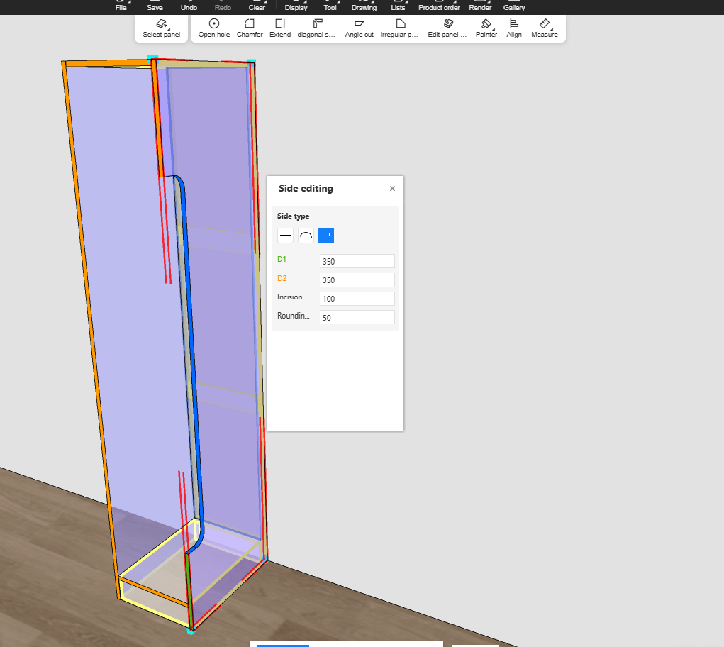
3.7 Special-Shaped Edge Banding Output Logic Optimization (for All)
Highlight:
When using "Panel Shape Edit - Side Edit" to modify an edge, the special-shaped edge inherits the original edge banding type.
Problem Solved:
In the old version, after edge editing, the edge banding type at special-shaped sections did not inherit correctly.
Feature Value: Improves user efficiency and experience.
Note: If a notch is created using functions other than "Edge Edit" (e.g., chamfering), it does not inherit the original edge banding type.
Steps:
Enter Cabinet Customization Mode-Drag and drop a cabinet
Press B key to select one of the panel, select one of the edge on the panel
Select the shape you would like to create

4. Finishing Customization
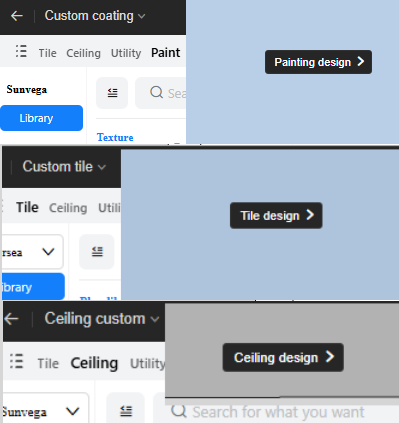
4.1 Unified Interaction For Entering 2D Design In Customization Modules (for All)
Highlight:
The entry point to enter the 2D immersive design page is now unified as a small black bar jump button.
Left-clicking on any wall (blank or with assets) displays this small black bar.
Problem Solved:
Previously, entry points to the 2D design page were inconsistent across modules. This update standardizes the left-click entry for Tiling, Ceiling/Wall, and Paint modules.
Feature Value:
Optimizes the interface, standardizes entry points, improving user satisfaction.
Steps:
Entry the Tile/Ceiling/Paint Module, single left click the wall.
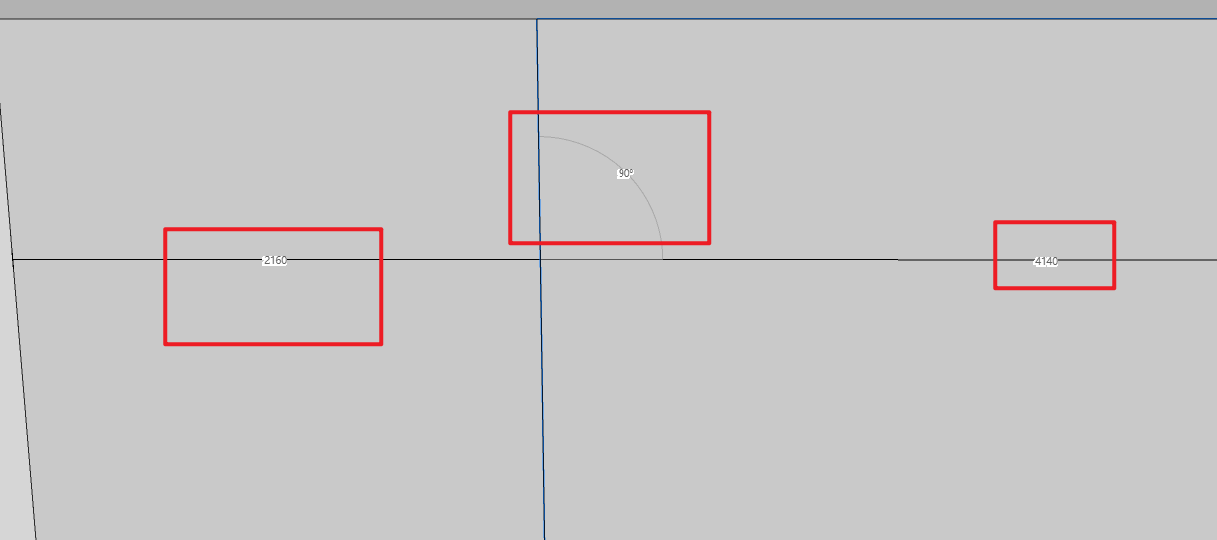
4.2 Quick selection of wall segmentation lines (for All)
Highlight:
Supports selecting segmentation lines for numerical modification even when not in segmentation line selection mode.
Problem Solved: Previously, after exiting segmentation line selection mode, users could not directly select a segmentation line segment to modify its values.
Feature Value:
Segmentation lines can now be selected by direct click. Once selected, an edit component (position ruler & angle) appears. Clicking inside the wall area of a segmented wall selects the wall operation. The two hot zones are independent.
Steps:
Single left click the wall under normal design module, select the scissor and left click the wall to draw a line

Double Right click to end the command. Left click on the line to change parameters
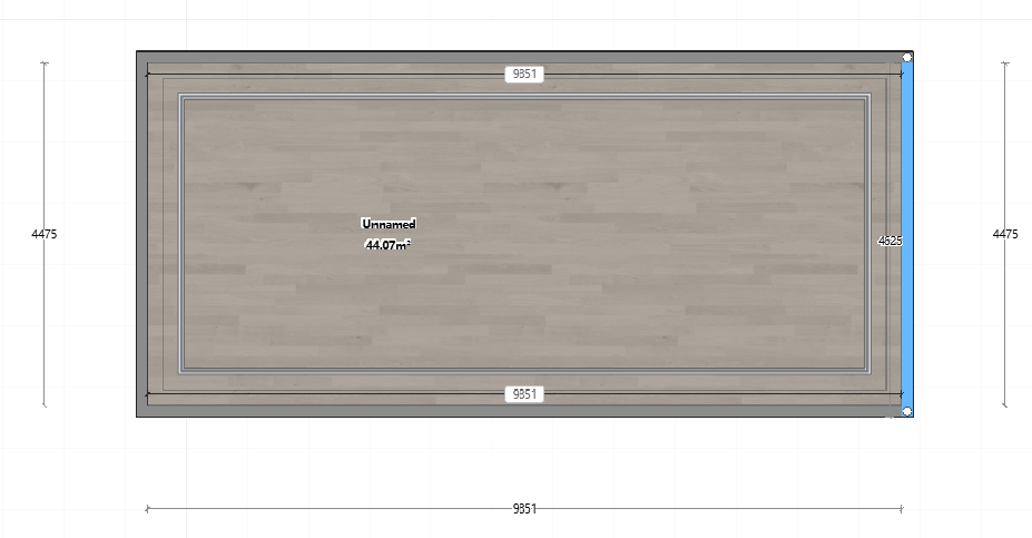
4.3 Parametric ceiling supports adaptive changes by area (for All)
Highlight:
Parametric ceilings now adapt according to area changes.
Problem Solved:
Previously, parametric ceilings could not adapt to area changes.
Feature Value:
Functional optimization improves user satisfaction.

Exit the ceiling module, drag and drop the wall to change the space dimension. The ceiling will change together.
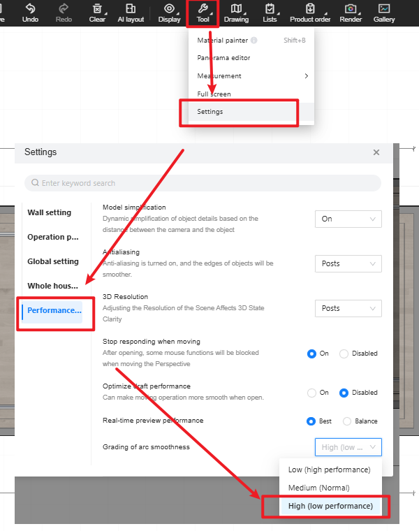
4.4 Ceiling/Wall increases arc line segment count setting (for All)
Highlight:
Increases the upper limit for arc segment count. The current maximum of 90 segments is expanded to 400 segments.
Added more intervals in the segment level setting bar, making transition smoother.
Problem Solved: Previously, arc lines in Ceiling/Wall customization might render unsmoothly.
Feature Value:
Previous three levels: Low: 30-90; Medium: 90-120; High: 150-150.
New three levels: Low: 30-90; Medium: 90-120; High: 150-600.
Steps:
Open Ceiling Menu -> Tools -> Settings.
Under Performance Settings, find Grading of arc smoothness (at the bottom).
Set to: High (Low Performance).

5. Aluminum Doors & Windows
5.1 Glass hole/notch function design (for All)
Highlight:
In aluminum door/window customization, glass holes are mainly for installing handles, locks, sensors, etc., while notches are for adapting to special structures like wall beams or irregular openings.
Digital hole/notch design can improve door/window design efficiency by 40%.
Problem Solved:
Previously could not meet glass hole/notch requirements.
Feature Value:
Enables visual design for various types of glass holes/notches, covering mainstream scenario needs.
Steps:
Enter the Aluminum Doors & Windows customization module, go to the 2D canvas.
Draw a door/window, select the fixed glass, right-click to enter Hole/Notch Mode.

In the top menu - Settings, set the default dimensions for holes/notches.

Select Hole (Shortcut: C) / Notch (Shortcut: R), click to place.

Perform hole/notch design on the fixed glass, click Save.

The 3D model updates with the holes/notches. Design is complete.

5.2 Ruler auto-jump function (for All)
Highlight:
When modifying a ruler dimension, pressing Enter confirms and automatically jumps to the next ruler in a counter-clockwise direction, allowing rapid sequential input.
Problem Solved:
Previously could not quickly type in multiple ruler values sequentially.
Feature Value:
Reduces the time users need to modify ruler dimensions.
Steps:
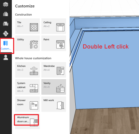
Enter the Aluminum Doors & Windows customization module, double left click the wall to the 2D canvas.
Draw a door/window
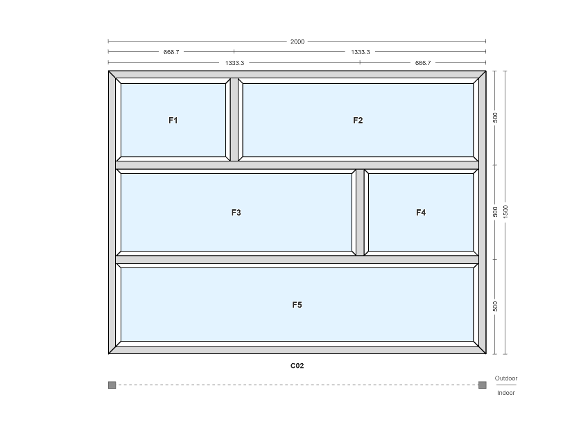
Select any side's ruler to modify.
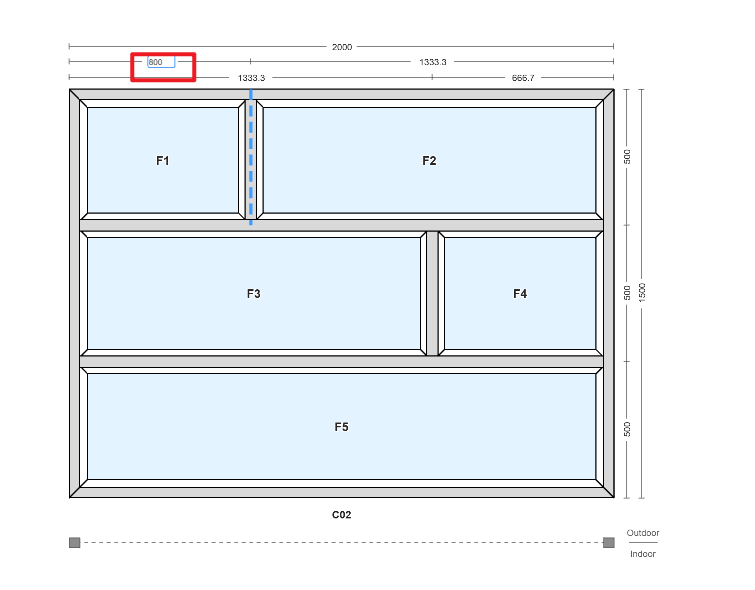
After modification, press Enter. The cursor automatically jumps to the next ruler counter-clockwise.
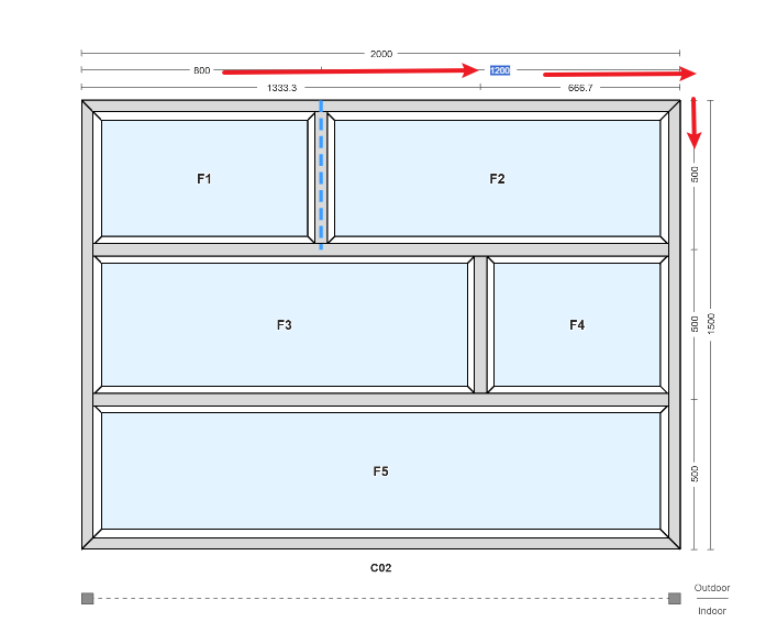
After the next modification is complete.
Click on a blank area or press Complete to exit edit mode.